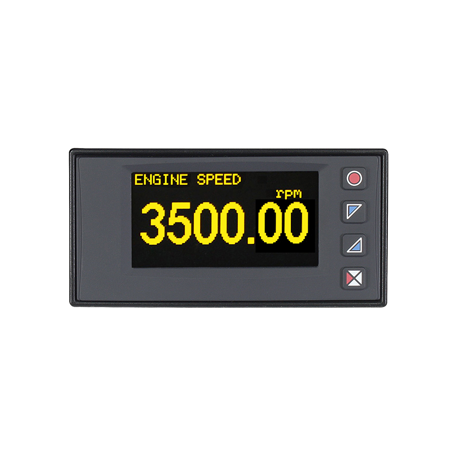
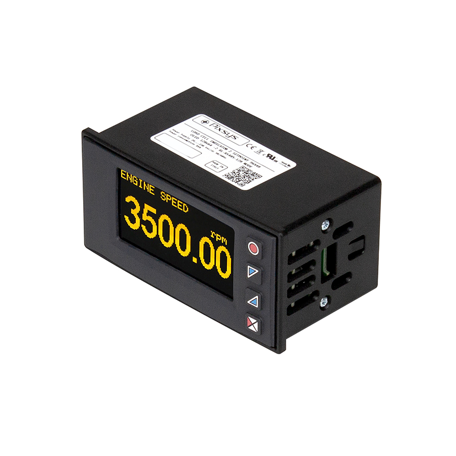
Indicator STR571 is designed as a flexible and fully customizable interface for sensors, I/O modules, signal converters, and generally for instrumentation with Modbus-RTU output signal.
The device allows up to eight variables to be read/written to Modbus slave devices, with representation of variables in both numeric and textual formats; both description and measuring unit for each variable can be freely set in alphanumeric characters, and if necessary, the data can also be rescaled in display. The number of variables displayed per page can be set from 1 to 4, with auto rescaling of font size and consequent number of pages.
In addition to the galvanically isolated Master serial port with Modbus RTU/Ascii protocol, a second Slave serial port makes querying from another Master possible.
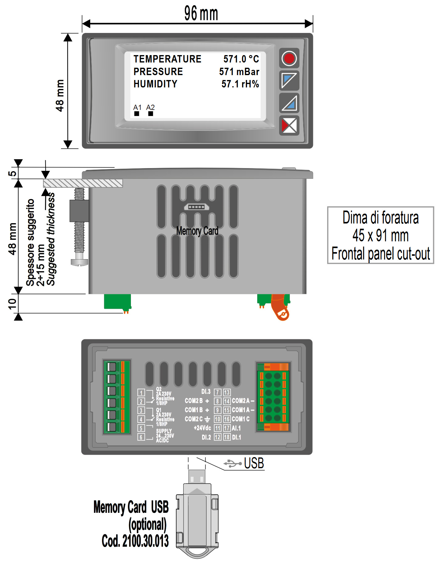
STR571 interface is quickly configurable via NFC with MyPixsys APP, without the need to power up the instrument or via multilingual text menus accessible by front keyboard. The device is equipped with a mini-USB port that allows programming also via software MyPixsysLab (see Software menu beside).
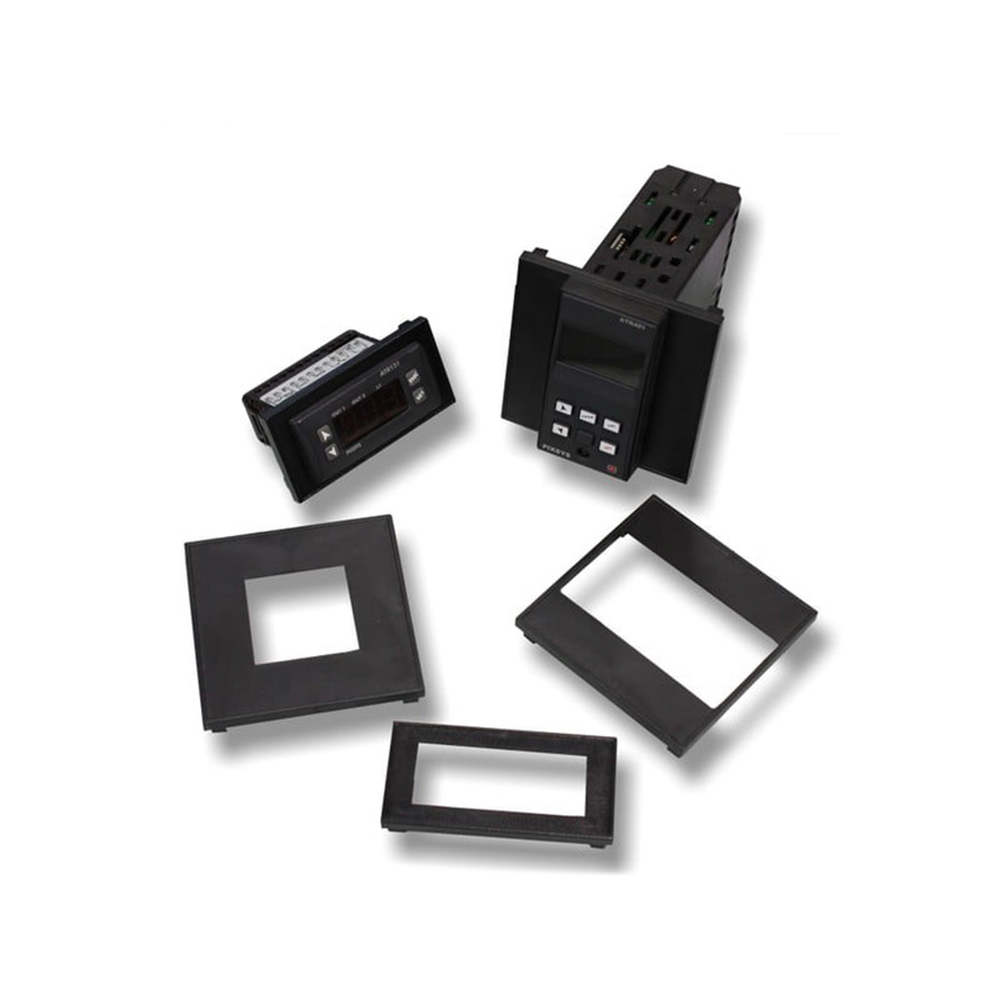
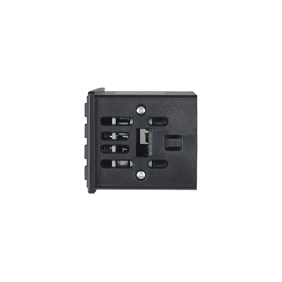
- Dimensions96x48 (Front) x 48 mm (1/8Din)
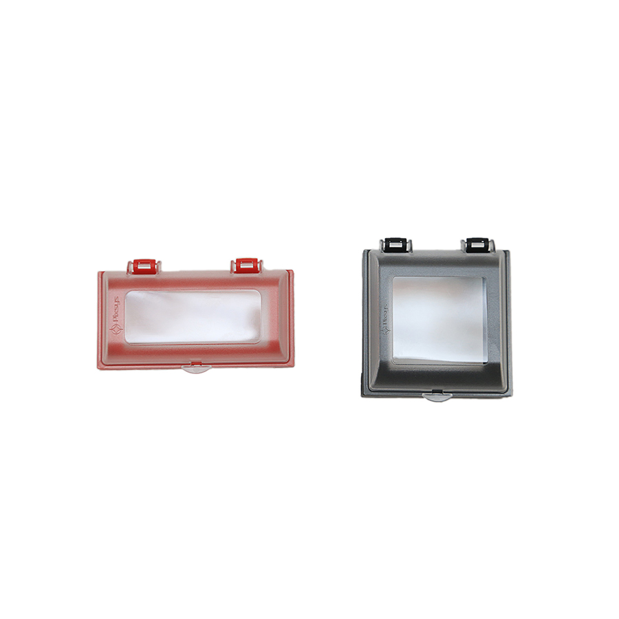
- MaterialBox: polycarbonate V0. Front mask: silicone rubber
- WeightApprox. 165 g
- SealingFront panel: IP54, Box and terminal blocks: IP20
- Operating conditionsTemperature 0-45 °C, humidity 35..95 RH%, max altitude 2000m
- CertificationsCE, UL
| ORDERING CODES | STR571-1ABC-T128R |
|---|---|
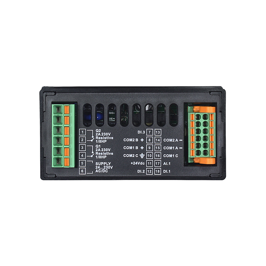
| Power supply | 24..230 V AC / DC ±15% 50/60 Hz - galvanic isolation 2,5KV |
| Power consumption | 6 Watt/Va |
| Display | 2.42" monochrome OLED graphic display (yellow), 128 x 64 |
| Potentiometer analogue input | min 1KΩ, 4096 points to set variable value |
| Digital inputs | 3 Digital 2 digital PNP/NPN inputs programmable to enable outputs, reset alarms, configuration lock, increase/decrease value, front panel encoder for surfing and changing input data. 1 PNP input programmable to select values |
| Analogue outputs | - |
| Auxiliary Outputs | 24VDC - 30mA max for external sensor power supply and potentiometer |
| Relais Outputs | 2x 2 A - 250 V AC resistive load |
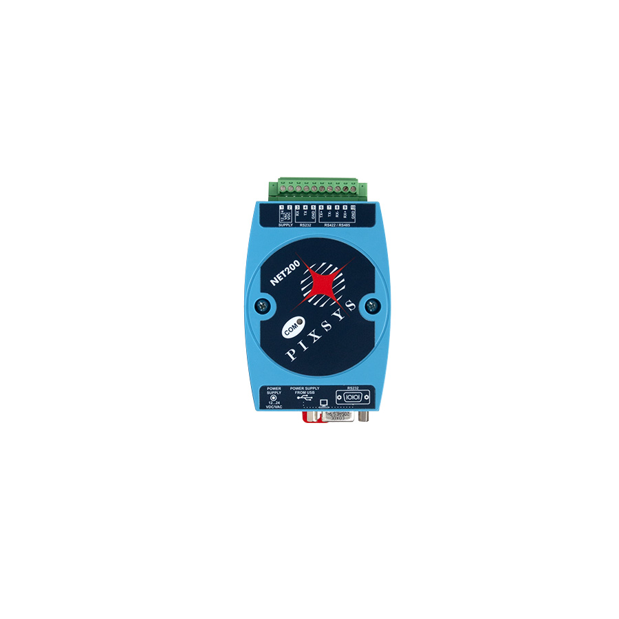
| Serial communication | 2x RS485 (1200..115200 Baud) galvanically isolated |
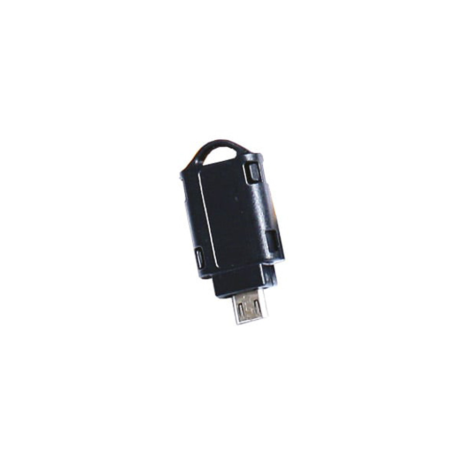
| USB | 1x micro USB for firmware programming |
- Communication protocols1x Modbus RTU Master 1x Modbus RTU Slave
- Variable managementManagement of up to 8 Modbus RTU 16 or 32 bit variables
- MultimasterConnect up to 16 Modbus RTU master devices on the same serial line
- Serial transmissionRetransmission of process values / setpoints / parameters on RS485 serial output
- Alarm modeAbsolute / Threshold, Band with instantaneous / Delayed / Retentive / by digital input activation, Activation by serial line
- Alarm function2 Alarms ON-OFF with hysteresis
- Display settings1..4 variables per page, max. 12 variables
- Process name and Setpoint displaySet as text value with max. 16 alphanumeric characters
- Measure unit visualizationSelection of the process unit to be displayed
- Multilingual menuEnglish/Italian/German/French/Spanish
- Data protectionLock of Command/Alarm Setpoints - Access to parameters by Password
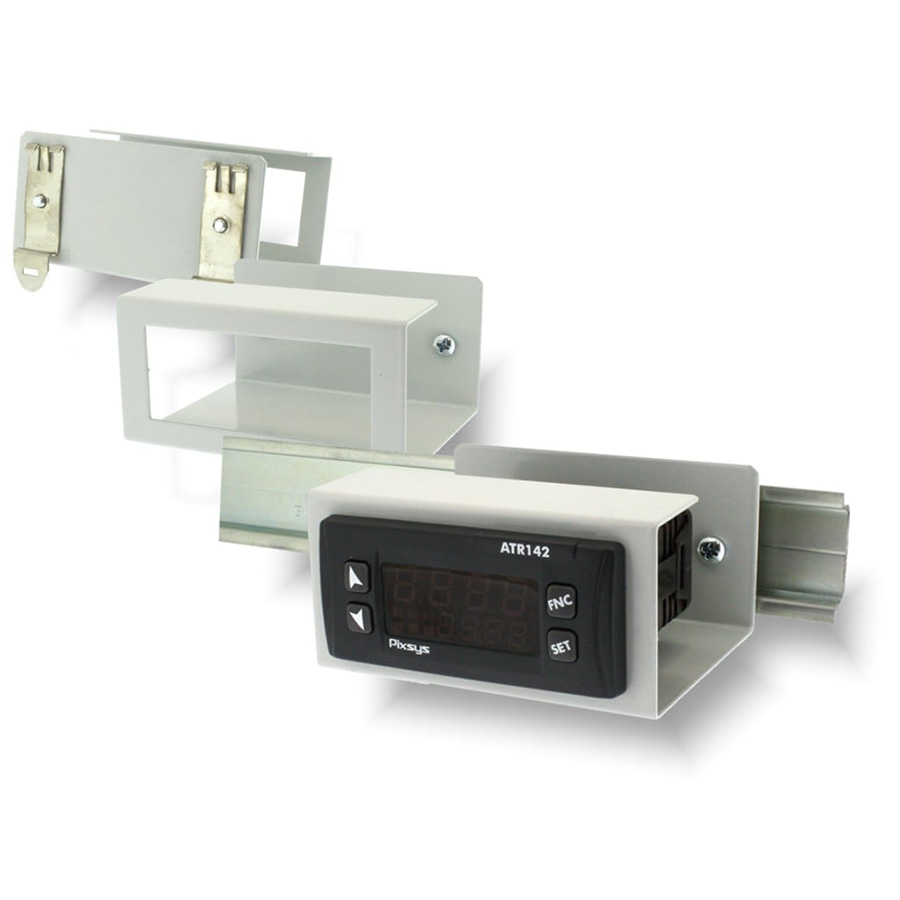
- STR571-1ABC-T128RMODBUS REMOTE DISPLAY 48x96 OLED RFID
2 RELAIS 3 ING. DIG. 1 ING. POT. 2 RS485