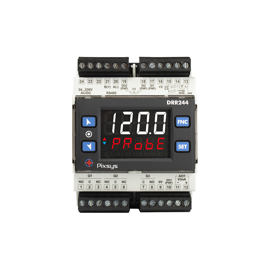
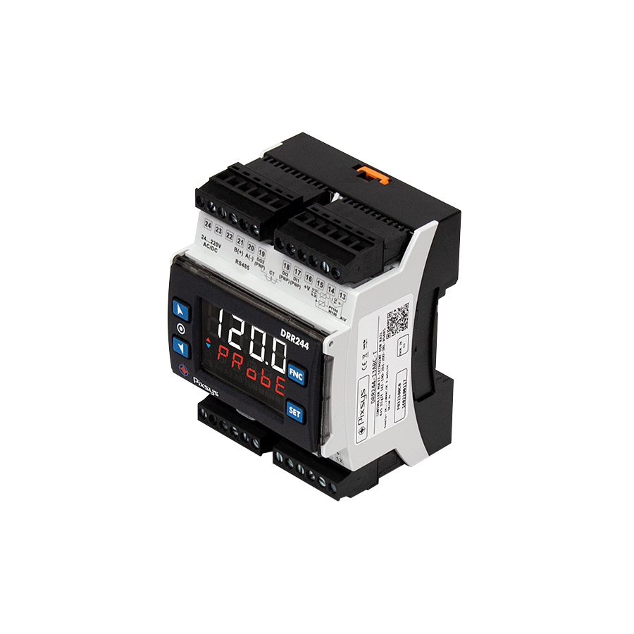
PID Controller DRR244 stands out in the DIN-rail controller segment thanks to its comprehensive hardware and software features resulting in a single order code.
The analog input is programmable for temperature sensors such as resistance thermometers and thermocouples, or for current/voltage process signals frequently used by pressure transmitters, humidity and flow sensors or inverters.
The outputs are selectable as command , multiple alarm modes or analogue retransmission.
For applications within networks the serial port is RS485 with Modbus RTU/ Slave protocol.
The extended range power supply from 24 to 230V AC/DC with galvanic isolation makes it suitable even in case of oscillation in the power grid.
In addition to its function as a hot-cold PID controller, DRR244 also finds application as a signal converter due to the availability of analog output galvanically isolated from the input, which can be used for retransmission of process value or setpoint .
Like the other models in the Blue Line series, DRR244 is programmable with MyPixsys App via NFC/RFID communication.
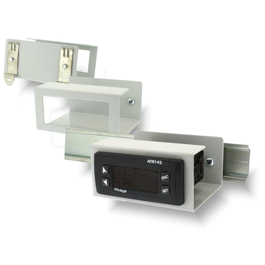
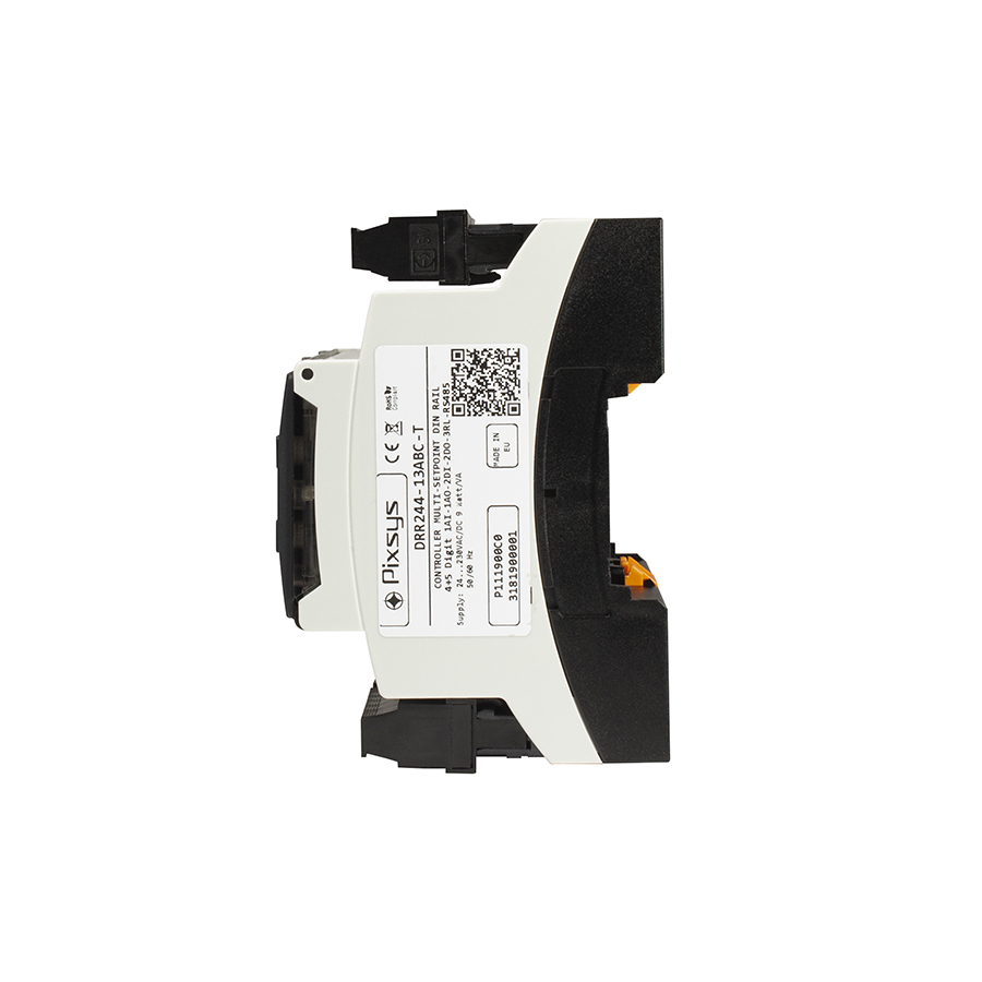
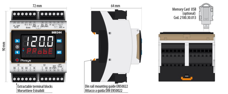
- Dimensions71 x 90 x 64 mm - 4 modules DIN43880
- MaterialBox: Polycarbonate V0; Front panel: self-extinguishing silicone rubber V0
- WeightApprox. 210 g
- SealingBox and terminal blocks: IP20
- Operating conditionsTemperature 0..45 °C, humidity 35..95 RH%
- CertificationsCE
- Control algorithmsON - OFF with hysteresis, P., P.I., P.I.D., P.D. time-proportioned
- TuningManual or automatic
- Alarm modeAbsolute/ threshold, band, upper/lower deviation, Alarms with optional manual reset and activation delay, Loop Break Alarm
- Dual PIDHeating / cooling with double PID
- Soft-StartRising gradient programmable as Degree / hour or fixed output %
- Open/Close logicsMotorised valves
- Software parameter configurationMemory Card, software MyPixsysLab, codici EASY-UP - Programming via APP (NFC) "MyPixsys" for Android and iOS devices
- Data protectionLock of control / alarm setpoint / Access to parameters by password
- Communication protocolsModbus RTU
- DRR244-13ABC-TTRIPLE-SETPOINT DIN RAIL CONTROLLER
4+5 digit 1AI-1AO-2DI-2DO-3RELAIS+RS485